Machine Design Interview Questions
 Download Machine Design Interview Questions PDF
Below are the list of Best Machine Design Interview Questions and Answers
It is a point at which the line if produced will meet or intersect a plane respectively.
- Horizontal Trace of the line: It is a point at which a line meets or intersects the horizontal plane. It is donated by the letter H.
- Vertical Trace of the line: It is a point at which a line meets or intersects the vertical plane. It is donated by the letter V.
In case when the line is parallel to both the horizontal plane and the vertical plane then there will be no trace on the planes.
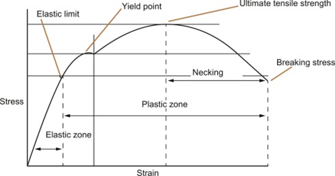
Before defining the Stress-Strain Curve, you must first understand what is stress and strain. Stress is defined as the ratio of the force divided by the cross-sectional area of the material to which the load is implemented. A Strain refers to the measure of the deformation of the material because of the applied force.
Now, the Stress-Strain curve is the graphical representation of the behavior of a material when the force is applied. In short, it is the curve that is produced by plotting stress and strain values under different loads. The fig is shown below:
It is the uppermost limit under which an endless number of loading cycles can be implemented to a material without causing the wear out. The endurance limit is also referred to as the Fatigue limit. In other words, endurance strength is determined as the maximum value of completely reversed bending stress that a material can endure without tire out after a number of cycles.
Adaptive design is one of the types of machine design which is extensively used. This is a process of modifying the existing technology into a better design. It uses the basic features and optimizes or retouches them so that the desired product gets better and can fit better to work with it. It is really hard and takes a lot of time to make a design from scratch. So, it not only saves money but also saves a lot of time.
Snap head rivets are two-piece rivets that are used to join two or more materials.
Below are some uses of Snap head rivets:
- Snap head rivets are mostly used in large structural work like manufacturing and construction.
- It is used to make a permanent joint in different applications.
- They are capable to provide support and strength to different products e.g. in boiler-making, and bridge girder construction.
- It is used to fasten materials like rubber, plastic, hardboard, metal, wood, etc.
- Snap head rivets are preferable because when the iron rivet cooled and contracted, the joint became more tightened.
- These rivets are lightweight and easy to use.
There are no specific rules for machine designing but it is not also a random process. Below are the important steps that are followed by the Engineer or Designer. Let’s have a look:
- Understand the Requirements: The primary step is understanding the purpose of the design. In this step, the designer makes a full list of the problems and a piece of brief information about the purpose or aim of the design for which the project is proposing.
- Analyze and Evaluate the Design Mechanism: In this process, designers analyze and draw the different mechanisms for the machine. After that, the best one gets selected and the rest are rejected.
- Analysis of Forces: The next step is analyzing every component of the machine. It needs to analyze how these parts fit in each other and what forces act on each component. In this step, the transmission of energy is also checked.
- Design of Elements: This step is very crucial in machine designing as a designer needs to check the different stresses acting in this operation. As we know, all the parts or components of the machine are subject to stress and because of this, these stresses become important to design the machine properly. This step is useful to design a machine that is durable and can endure the stress properly.
- Material Analysis and Selection: Selection of appropriate material for the machine component is another step after the stress analyzed.
- Design Iteration for Manufacturing: Design can be changed without affecting the machine’s performance. This process helps in the easy manufacturing of the product.
- Creation of Detailed Mechanical Drawings: The next step is the creation of drawing with every little detail. This step also involves the assembly of the machine. Using the CAD capabilities for the details can play a big role in this process.
Machine design is referred to creating a machine or structure by using imagination, scientific principles and engineering techniques. A machine is designed in such a way that it satisfies the needs of a customer. It tells the basic idea How a machine will look and perform the function. Machine design focuses on three main areas i.e. mechanical behavior, machine element and manufacturing process.
Ductility is defined as the capacity of a material to be deformed plastically without fracture. This property indicates the softness and malleability of the material. It basically depends on the nature of the material.
Impact load is defined as the force delivered by the sudden load on a structural member rather than a force applied constantly and sustained over a long period.
For e.g.
Throwing a bundle of wood from the 20th floor on the ground instead of simply placing it. The formula to calculate the impact load is the total kinetic energy dissipation divided by local deformation.
The various phases of a design process are as follows:
- Study the Client Brief.
- Research, Research, Research.
- Brainstorm.
- Concept Development.
- Revisions.
- Completion.
- Testing.
In mechanical engineering, tolerance is the limit of how far a true measurement can change from what's planned. It is done to achieve proper functionality and to ensure that the final product is worth using. It is difficult to create tolerance and it is only measured by the experts.
There are two major tolerances:
- Physical measurement (dimensions)
- Attribute (time, temperature, sound level).
Engineering drawing is used to accurately catch all geometric features of an item. It helps the manufacturer or engineer to produce the desired product. Engineering drawing is not merely drawing of pictures but it is a graphical language used to transmit information from engineers to the worker.
Engineer drawing is very useful in defining the size, the shape of the product or its component. Engineer drawing also puts a light on information about acceptable variations, materials, load limits, and any other valuable information that define the property of the material.
There are many types of screws that are used for several purposes. Some of them are mentioned below:
- Wood screws: As the name suggests, wood screws are used to join two or more solid objects together. Their sharp pointer allows them to dig deep into the wood. Therefore, wood screws play a great role in woodworking applications.
- Machine screws: A machine screw is a type of screw that is extremely useful in machining applications. The function of the machine screws is to hold the heavy-duty metal objects together. Machine screws are bigger than any other type of screws.
- Concrete screw: This screw is made of stainless or carbon steel and is widely used for fastening materials to concrete.
- Masonry screw: This type of screws mostly have a blue color coating and as the name suggests, it is used to insert a pilot hole in masonry.
- Double-ended (dowel) screw: This type of screw has two pointed ends and no head. This screw is mostly used for making hidden joints between two pieces of timber.
- Drywall screw: This type of screw can easily be recognized as they are coated with black phosphate and designed with a bugle head. It is used to attach drywall to timber or metal studs.
There are some other types of screws like Drive screw, Eyebolt, Decking screw, lag screw, chipboard screw, mirror screw, twin fast screw, security head screw, etc. which are widely used.
Under the action of stress, the object or material is separated into two or more pieces, this process is known as Fracture. Within the solid, because of the development of certain displacement discontinuity surfaces fracture occurs.
- Ductile fracture: It is done because of the large amount of plastic deformation before the parts can fail. The cross-section of the material is reduced after the failure. At the latter part, you can observe the shear lips which means the part is failed. The surface of the part now gives a dull and fibrous appearance
- Brittle fracture: Unlike Ductile fracture, no plastic deformation takes place before fracture in Brittle fracture. In comparison with the Ductile fracture Brittle fracture usually occurs at high speeds and involves little energy absorption. The characteristics of brittle fracture can be seen with very little plastic deformation and a shiny fracture surface. You can observe the brittle failure starts at a notch or stress concentration and spread with plastic deformation
The S-N curve describes the relationship between cyclic stress amplitude and the number of cycles to failure. On the horizontal axis, N describes the number of cycles to failure is given (on the logarithmic scale) whereas on the vertical axis, S describes the stress amplitude of the cycle.
Curved beam, as clear from the name itself, includes any structural member like arches, chain links, etc. which must have a significant amount of curvature in the plane of loading. In short, we can say that a Curve beam is a beam that is covered by circular arcs in every direction.
The curved beam can be further divided into two parts:
- Beam with small initial curvature
- Beam with large initial curvature
The type of the beam can be distinguished by calculating the ratio of the initial radius of curvature to the depth of the section. If the ratio is greater than 10 then it fits in a beam with small initial curvature and if the ratio is less than 10 then it comes under a beam with large initial curvature category.
GD&T stands for Geometric Dimensioning and tolerancing which work as a system to define the relation between part features and measurement references. Engineers and designers make use of this international language to describe the part features. They describe the part characteristics by virtue of size, orientation, form, and location. It gives information about the degree of accuracy of each feature of the part. Moreover, it also defines the possible variation that can be made in the form and features.
Injection moulding is a process to get the product in the desired shape. This process is done by adding molten material into a mould. A number of materials used for this for e.g. metals, glasses, most commonly thermoplastic and thermosetting polymers, confection, and elastomers.
After the material is added to the mould, it is allowed to cool and hardens. An engineer or industrial designer then gives design to the product in a desirable way. Industrial moulding is done to make a number of products with complicated shapes.
This process has the following 6 major steps: -
- Clamping
- Injecting
- Dwelling
- Cooling
- Mould opening
- Removal of products
In sketch or drawing, ordinate dimensions are a set of dimensions from a zero ordinate. Ordinate dimensions are considered as reference dimensions which means it is not possible to change or use their value to drive the model.
The type of ordinate dimension whether it is horizontal or vertical is determined by the orientation of the points that you select. It depends on your selection where you want to add the ordinate dimension.
It is used as a reference on a part if the reference doesn't exist already. In the absence of an appropriate planar surface, it is possible to sketch or place a feature on a datum plane. If it were an edge you can dimension to a datum place. You can also utilize a datum plane while constructing an assembly.
Although the size of the Datum plane is infinite, it is really easy to resize them to fit part, feature, axis, surface, edge or the measurement of the display outline of the datum plane
Also Read Related Machine Design Interview Questions | ||
|---|---|---|
| Hydraulic Mechanics Interview Questions | Thermodynamics Interview Questions | |
| Power Plant Engineering Interview Questions | IC Engine Interview Questions | |
Latest Interview Questions-
Silverlight Interview Questions
-
Entity framework interview questions
-
LINQ Interview Questions
-
MVC Interview Questions
-
ADO.Net Interview Questions
-
VB.Net Interview Questions
-
Microservices Interview Questions
-
Power Bi Interview Questions
-
Core Java Interview Questions
-
Kotlin Interview Questions
-
JavaScript Interview Questions
-
Java collections Interview Questions
-
Automation Testing Interview Questions
-
Vue.js Interview Questions
-
Web Designing Interview Questions
-
PPC Interview Questions
-
Python Interview Questions
-
Objective C Interview Questions
-
Swift Interview Questions
-
Android Interview Questions
-
IOS Interview Questions
-
UI5 interview questions
-
Raspberry Pi Interview Questions
-
IoT Interview Questions
-
HTML Interview Questions
-
Tailwind CSS Interview Questions
-
Flutter Interview Questions
-
IONIC Framework Interview Questions
-
Solidity Interview Questions
-
React Js Interview Questions
Subscribe Our NewsLetter
Never Miss an Articles from us.
Join Onlineinterviewquestions.com
Create your account to comment, follow, share link / Article and Download PDF's.
